Design / Eval boards, substrates, interposers
We design the board.
We build the package.
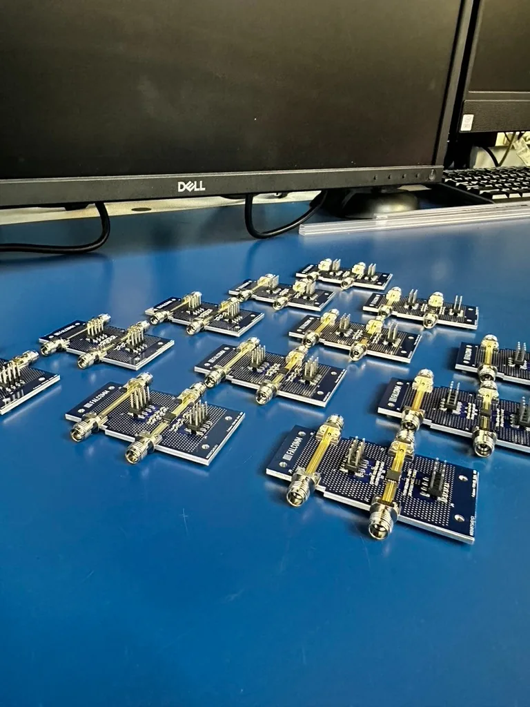
RF evaluation boards, package substrates, interposers and chip-on-board test vehicles — laid out on aluminum nitride, 96% alumina, RO4003C, RT/duroid and polyimide build-up HDI, then attached, wire bonded and inspected on the same site.
/ Eval board / Substrate / Interposer / Test vehicle / US-soil
We design the board.
We do not design the die.
Heisler designs eval boards, package substrates and interposers. Heisler does not design the die or the integrated circuit.
That boundary is deliberate, and it is why the two halves fit together. You own the silicon. We own everything it lands on — the carrier, the routing, the launch, the bond pads, the fixture — and then we build it, because the people who set pad pitch and layer stack are the people who run the bonder.
Bring a die and a datasheet, a block diagram, or a target spec. If the die is still in design, send the pad map when you have it.
Design capability
RF eval boards, package substrates, interposers.
Four artifacts and the firmware that exercises them. Each one is drawn to be built on the floor downstairs.
Pad pitch, layer stack, thermal path and test access are set with the bonder, the laser and the X-ray in the room — not handed to a separate shop and discovered on the first lot.
Program-specific design rules and stack-up detail under NDA.
- 01RF evaluation board — grounded coplanar or microstrip launch, bias networks and connectors, on RO4003C, RT/duroid or an aluminum nitride carrier, so a high-frequency die can be characterized on the bench.
- 02Package substrate — thick-film and thin-film ceramic on aluminum nitride and 96% alumina, or organic build-up, with bond fingers and escape routing drawn to the wire-bond rules we bond to. Flip-chip BGA substrates: Custom ASIC FCBGA.
- 03Interposer — the routing layer between chiplets and side-by-side die, in polyimide build-up HDI or ceramic, feeding straight into 3D and heterogeneous integration.
- 04Chip-on-board test vehicle — the structure that proves the hard part of the process before it ships: die attach, bond finger geometry, loop control, and the inspection that scores it.
- 05Firmware and bench bring-up — embedded control and the test routines that exercise the board once the die is on it.
- 06Design-rule checking — automated design-rule checking against the fabricator's own rule deck on every release, run alongside the assembly rules, so fabrication and the bonder agree before anything is ordered.
Rules, published
The design rules we design to.
These are industry design rules — published standards and supplier datasheets — not Heisler process limits. They are the constraints a layout has to clear before it is worth fabricating, and each one has a full table on the page where it belongs.
| Rule | Value | Source | Full table |
|---|---|---|---|
| Bond finger length | 0.6 to 0.8 mm | Die Products Consortium, PCB design guidelines for chip-on-board | Wire bond |
| Bond finger pad definition | NSMD, solder-mask clearance 50 µm minimum | ECSS-Q-ST-70-12C Rev.1, requirement 1200538 | Wire bond · 3D & HI |
| Microvia opening and aspect ratio | 175 µm top opening as-designed, aspect ratio 0.8 maximum | ECSS-Q-ST-70-12C Rev.1, §11.4.2 | 3D & heterogeneous integration |
| RO4003C dielectric constant | design Dk 3.55, process Dk 3.38 ±0.05, Df 0.0027 at 10 GHz | Rogers RO4000 datasheet | Materials & substrates |
| ENIG loss on grounded coplanar waveguide | about 1.2 dB per inch | IPC, Effects of PCB Fabrication on High-Frequency Performance | Materials & substrates |
Sources: Die Products Consortium · ECSS-Q-ST-70-12C Rev.1 · Rogers RO4000 datasheet · IPC, Effects of PCB Fabrication on High-Frequency Performance. Published industry rules and material data, not Heisler capability numbers.
What it is drawn on
AlN, alumina, RO4003C, RT/duroid, polyimide HDI.
Material choice is a design decision, and on an RF board it is usually the first one.
Aluminum nitride is the carrier when heat is the argument: roughly five to seven times the thermal conductivity of alumina, with an expansion coefficient close to a GaN-on-SiC die. 96% alumina is the thick-film workhorse. RO4003C is the general-purpose low-loss laminate that still presses like a normal multilayer, RT/duroid is where the link budget is the whole argument, and polyimide build-up HDI is where fine-line organic routing and microvias belong.
Two design choices that cost decibels rather than dollars: use RO4003C's design Dk of 3.55 rather than its process Dk of 3.38, or a 50 Ω line lands high; and keep a soldermask and an ENIG finish off a long RF run, because ENIG costs about 1.2 dB per inch on grounded coplanar waveguide.
Published Dk, Df, thermal conductivity and CTE for every material above — with the mixed-frequency caveats spelled out — are in the table on Materials & substrates.
Design hands off to the floor.
A finished design only matters if someone can build it. The same team that drew the board attaches the die to it — here are the lines it lands on.
How we engage
Start where it hurts.
You do not have to hand us the whole thing.
Pick up at layout, at the test vehicle, or at packaging — whichever step your program cannot get past. Prototype and low-volume programs are welcome, and starting small does not cap where the program can go.
It is the same discipline we apply to process development in Engineering & AI — DOE, SPC and data-driven control — pulled forward to the design stage so risk is retired before scale-up.
Software + hardware co-design
The people who write the firmware draw the board.
Firmware and hardware are developed against each other, not thrown over a wall. The team that lays out the board writes the bring-up code and the test routines that exercise it — and packaging and inspection sit in that loop from the first revision.
From co-design to a launched, volume-qualified product — one team, one schedule.
Watch / Co-design
Why co-design beats trial-and-error.
Co-designing the process alongside the device closes the loop — lower cost, higher yield — instead of iterating blind. One team from concept to a shippable build, so your capital stays in the product.
Watch on YouTube → Why co-design beats trial-and-error prototyping · See concept-to-launch product realization →
Questions engineers ask
Design, packaging, and the line between them.
Do you design the die or the IC?
No. Heisler designs RF evaluation boards, package substrates, interposers and chip-on-board test vehicles. We do not design the die or the integrated circuit. Send us the die and the datasheet and we design the package and the board around it, then build it.
What do you actually deliver?
An RF evaluation board, a package substrate, an interposer, or a chip-on-board test vehicle, released as a fabrication and assembly package. The same team then attaches the die, wire bonds it and inspects it on the same site.
What materials do you design on?
Aluminum nitride and 96 percent alumina for ceramic carriers, RO4003C and RT/duroid for low-loss RF laminate, and polyimide build-up HDI for fine-line organic work. Published properties for each material are in the table on our materials page.
How is a layout checked before it is released?
Automated design-rule checking against the fabricator's own rule deck, run on every release, alongside the assembly rules we bond and attach to every day. Checking both decks together means a layout that passes fabrication also passes the bonder.
Are the numbers on this page your process limits?
No. The table on this page is industry design rules taken from published standards and supplier datasheets. They are the rules we design to, not Heisler process limits. Program-specific limits are covered under NDA.
Can you design the board and package the part?
Yes, that is the whole point. Design, die attach, wire bond and inspection happen under one roof in the United States, so a packaging constraint becomes a design change in the same week instead of a returned lot and a new purchase order.
Process More.
Send us the die
and the datasheet.
We will come back with a carrier, a stack-up and a board — and then we build it. One team from pad map to qualified hardware, on US soil.
/ US-soil / traceable / NDA on request