Advanced Packaging / Wire Bond
Wire Bonding That Passes Screening.
Semiconductor wire bonding — gold ball, aluminum wedge, and ribbon interconnect, from fine-pitch die-to-substrate to heavy aluminum power loops. Bond programs developed with pull and shear verification, qualified to the standards your hardware ships under. Also written wirebond or wirebonding — same solid-state weld, same lab.
/ Au ball · Al wedge · ribbon / fluxless / MIL-STD when required / US-soil
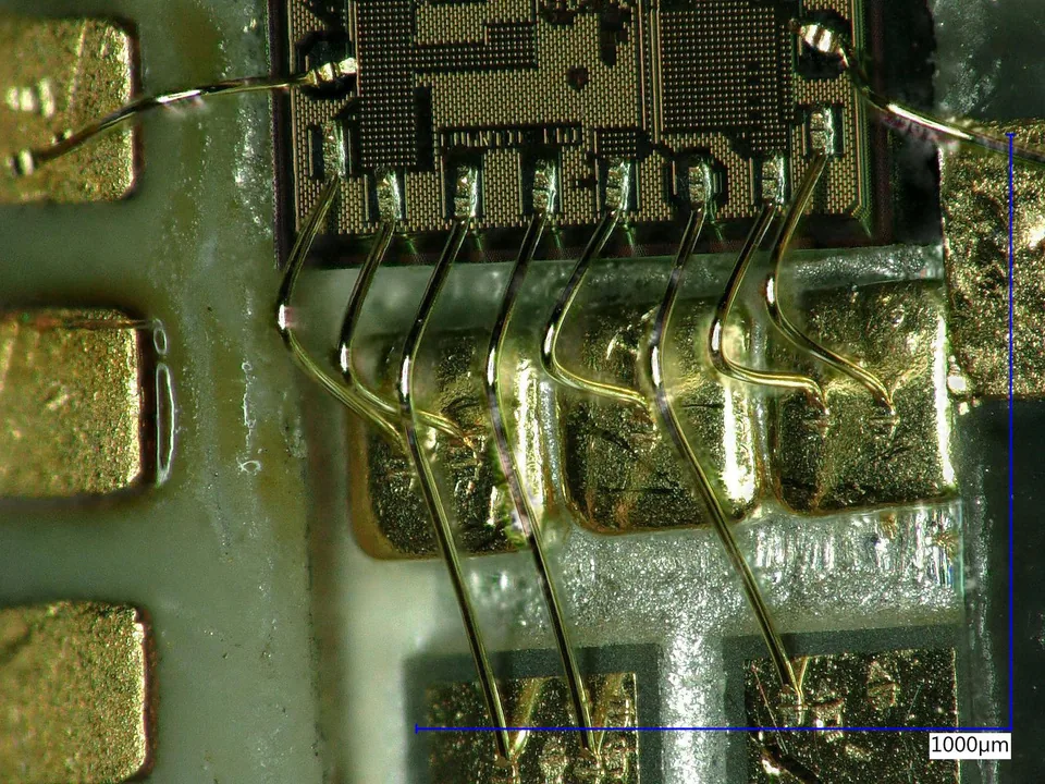
Proof, from real builds
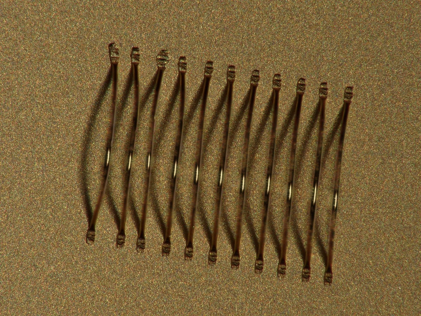
Gold and aluminum wire — ball, wedge & ribbon bond
Lead-frame, substrate, PCB, die-to-die
Wafer formats handled · die-to-substrate, PCB & lead-frame
Pull/shear distributions, bond schedules, and qualification data available under NDA.
Types of wire bonding
Ball, wedge, and everything between.
One bonding cell, both metallurgies. We match the bond — gold thermosonic ball or aluminum ultrasonic wedge — to the pad, the pitch, the current, and the reliability target, not to whatever the shop happens to run.
Fine-pitch signal routing and heavy-wire power loops come off the same engineering team that develops the program and signs off the data.
- 01Gold ball bonding — thermosonic, fine-pitch signal interconnect for die-to-substrate and die-to-die.
- 02Aluminum wedge bonding — ultrasonic, low-temperature for Al-pad and temperature-sensitive devices, through to heavy aluminum wire for high-current power loops.
- 03Ribbon bonding — low-inductance flat-ribbon interconnect as an alternative to round wire; ribbon sizes on request.
- 04Fine-pitch routing — 15–50µm gold and aluminum wire, fine-pitch bonding on the ASM AERO Eagle platform where loop control and placement decide the yield.
- 05Fluxless interconnect — clean assembly with no post-attach residue to remove.
- 06Substrate flexibility — die to substrate, PCB, lead-frame, AlN, and ceramic carriers.
Au + Al wire 15–50µm · ball, wedge & ribbon · signal to power · 2″–12″ wafers · die-to-substrate / PCB / lead-frame.
How the weld is made
Three ways to weld a wire.
Wire bonding is a solid-state weld made from some mix of heat, force, and ultrasonic energy. The mix defines the method, and the method sets what pad metal, wire, and temperature budget a device can take. This is the general engineering picture; how Heisler dials each one in per device is in the process-control section below.
Thermocompression
Heat plus force, no ultrasonic. The classic gold ball bond, but it needs a hot substrate — often 300°C and up — to form the weld. That thermal budget rules out temperature-sensitive die, which is why pure thermocompression is now rare.
Ultrasonic
Force plus ultrasonic scrubbing at room temperature, no substrate heat. The standard route for aluminum wedge bonding and heavy-wire power loops, and the friendly option for die that cannot see a hot stage.
Thermosonic
Heat, force, and ultrasonic together. Moderate stage heat — well below thermocompression — plus ultrasonic energy makes a reliable gold ball bond at a temperature the die survives. It is the workhorse for fine-pitch gold today.
Gold or aluminum
Gold and aluminum wire bonding.
- →Noble metal, no surface oxide, so it ball-bonds cleanly by thermosonic.
- →Holds fine pitch and forms round, formable loops with strong, repeatable shapes.
- →On aluminum pads it grows gold-aluminum intermetallics, so the thermal budget has to be bounded (see failure modes below).
- →Ultrasonic wedge at room temperature, no stage heat needed.
- →Matches aluminum bond pads metal-to-metal, avoiding the gold-aluminum couple.
- →Scales to heavy wire for high-current power loops that fine gold cannot carry.
Heisler runs gold thermosonic, aluminum ultrasonic, and ribbon bonding in one cell, and picks per pad metal, pitch, current, and reliability target — advanced packaging engineering owns that call.
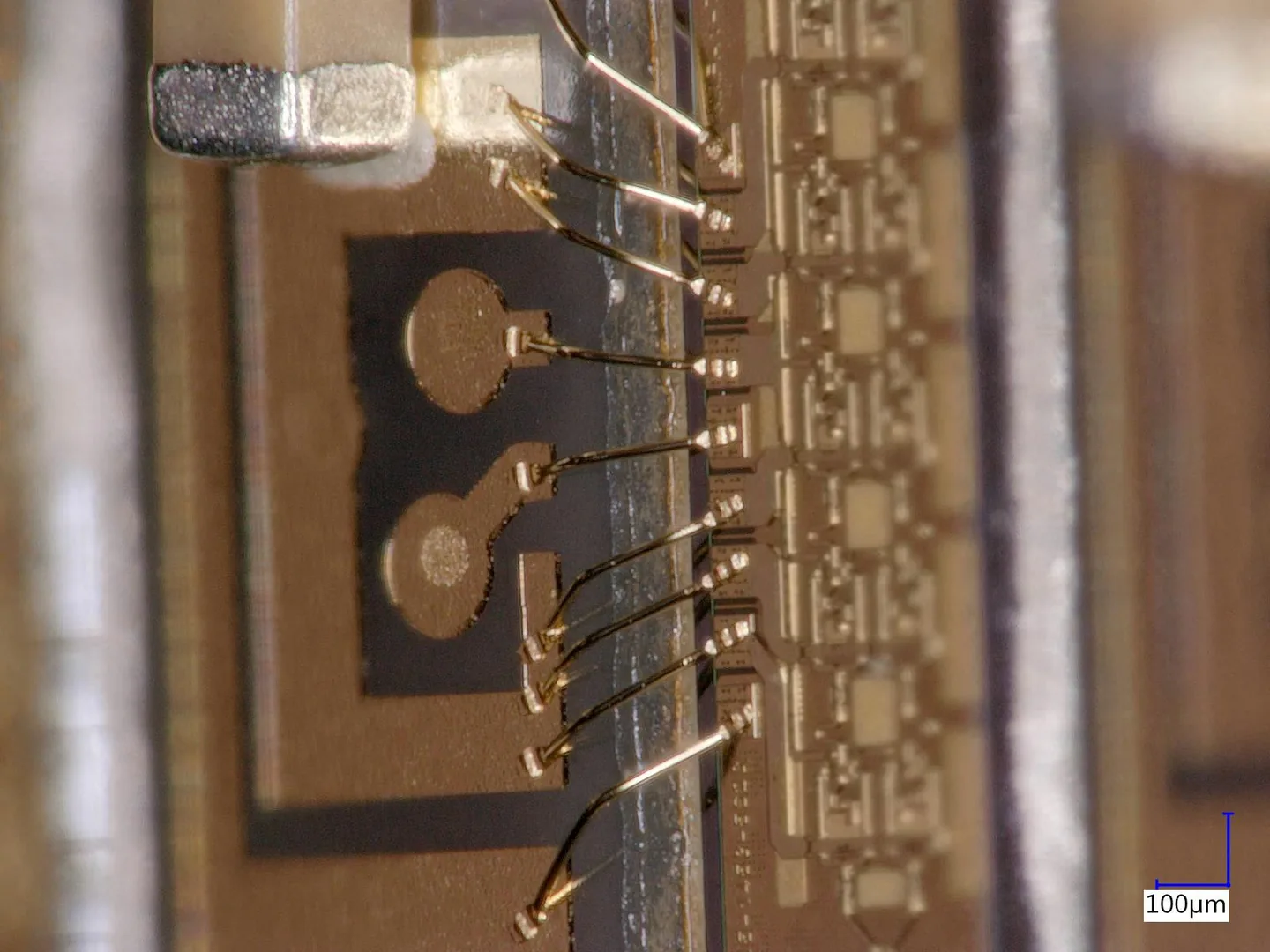
Process control
A bond is data, not a guess.
Program development
Force, ultrasonic energy, time, and temperature dialed in per device — then locked as a documented schedule.
Loop control
Loop height and profile managed for clearance, span, and reliability — no shorts, no strain at the heel.
Pull & shear
Destructive pull testing to MIL-STD-883 Method 2011 and ball-bond shear testing to MIL-STD-883 Method 2037, with failure-mode capture, not just a pass count — production wire bonds typically run 3–4× the standard minimum pull strength.
DOE-driven
New devices run through structured DOE so the process window is found by data, not by re-bonding until it sticks. See how we develop →
Every adjustment stays traceable and tied to the pull/shear distribution it produced.
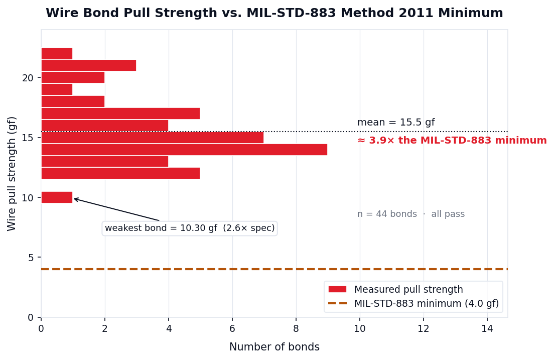
Representative wire-bond pull-test batch (n=44) against the MIL-STD-883 Method 2011 minimum.
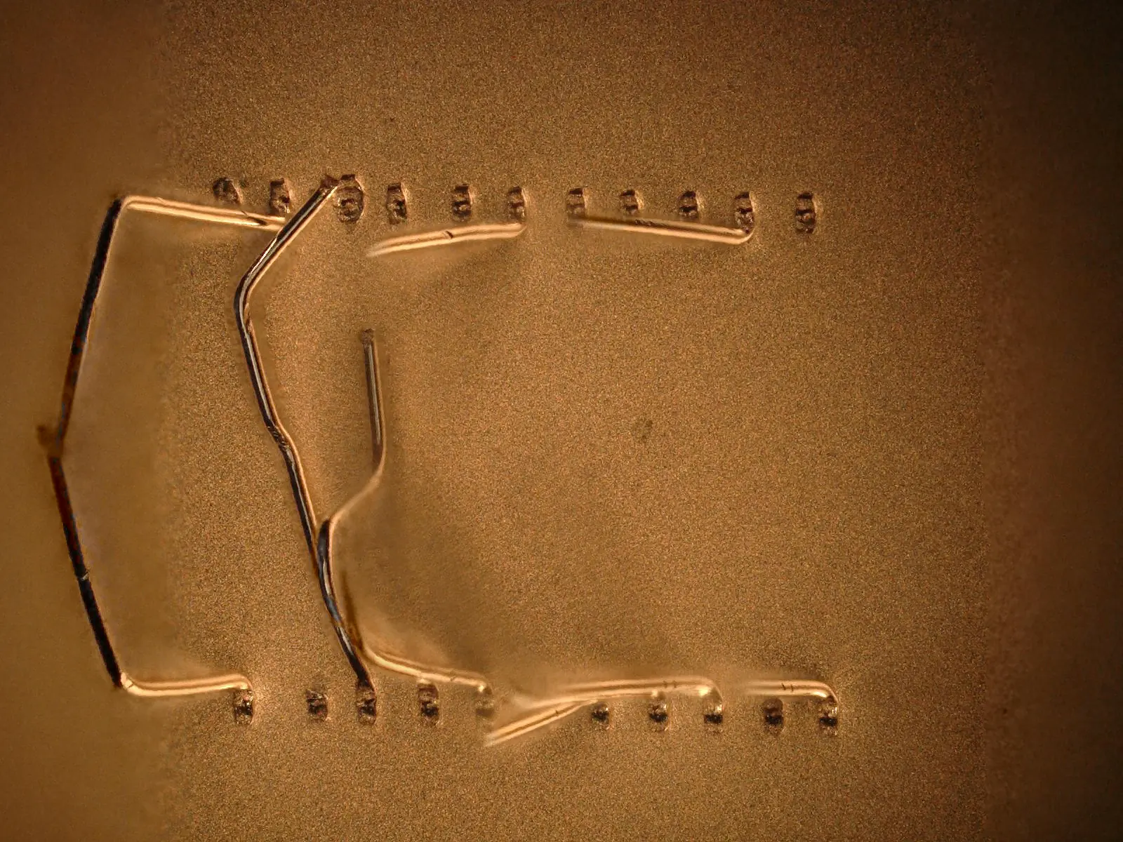
Before the bonder runs
Substrate-side design rules for wire bond.
Half of a wire-bond yield problem is decided in the substrate artwork, before the bonder ever runs. A bond finger is sized from the deformed bond plus the bonder’s placement error on both sides, not from the wire diameter. These are the published industry rules we design to, and what we check your artwork against at design review.
| Rule | Value | Applies to | Why it binds |
|---|---|---|---|
| Bond finger length | 0.6 to 0.8 mm | Wire-bond fingers on chip-on-board substrates | Long enough to land the deformed bond and still leave the capillary or wedge room to touch down and pull away clean. |
| Aluminum wedge bond footprint | Length 1.5 to 5.0 wire diameters, width 1.2 to 2.5 wire diameters | Aluminum ultrasonic wedge bonds | The deformed bond, not the wire, sets the pad it has to sit on. Below the lower limit the weld is starved; above the upper limit it is over-deformed and the heel goes thin. |
| Deformed bond envelope at 25 µm wire | Width under 62.5 µm, length under 125 µm | 25 µm (1 mil) wire, the common fine-pitch case | Turns the ratio rule into a number you can draw. This is what the finger has to contain before placement tolerance is added on either side. |
| Wire length ceiling | 5 mm, and no more than 100 wire diameters — so 2.0 mm at 20 µm wire | Every unsupported span in a chip-on-board loop | Two limits, whichever is shorter. Long wire sags and loses loop control; on fine wire the diameter-based limit is the one that actually binds. |
| Finger-to-die-paddle standoff | 0.4 to 0.75 mm | Gap from the die-attach paddle edge to the nearest bond finger | Keeps the bond tool clear of the die edge and the die-attach fillet, and keeps the loop off the die corner. |
| Bond finger pad definition | NSMD, solder-mask clearance at least 50 µm | Solder-mask-over-copper substrates | A mask-defined finger puts the bond on a mask ledge and buries the copper edge. NSMD with real clearance keeps the bond on metal and keeps mask registration error out of the bond area. |
| Unsupported span, 30 µm gold loops | Keep spans at or under 75 mil (1.9 mm) | Long unsupported gold loops that see mechanical shock | Measured, not estimated: 30 µm gold loops shorted at a 2.5 mm span under shock and survived at 1.9 mm. Span, not wire strength, is what fails first. |
Sources: Die Products Consortium, PCB Design Guidelines for Chip-on-Board; ECSS-Q-ST-70-12C Rev.1; G. Harman, Wire Bonding in Microelectronics, 3rd ed. These are industry design rules we design to, not Heisler process limits — send the pad map and we will mark up the artwork against them.
Reliability by design
The failure modes we design out.
A wire bond fails in known ways. We keep those mechanisms out of the process window when we develop the schedule, then screen to prove they stayed out.
Gold-aluminum intermetallics
Where gold meets aluminum, intermetallic phases grow by diffusion, including the brittle AuAl2 known as "purple plague," and Kirkendall voiding can hollow the interface. Growth is driven by temperature and time, so we bound the thermal budget in bonding and cure, match wire to pad metallurgy, and run thermal-cycle stress to expose any intermetallic weakness before your hardware ships, not after.
Cratering
Too much ultrasonic energy or bond force fractures the silicon under the pad, a crater, worst at the bond perimeter, that a pull test alone can miss. The developed schedule bounds force and energy to seat the bond without cracking the die. Compound semiconductors like GaAs fracture at roughly half the strength of silicon, so the window is set tighter and verified on the actual substrate.
Heel cracking, intermetallics, and cratering are screened for on the same data package that ships with your build.
Qualification & reliability
Built to survive the screen.
A bond that looks good and a bond that survives 1,000 thermal cycles are different bonds. We develop to the second one. Screening and environmental stress are part of the build, not an afterthought handed to someone else.
MIL-STD screening
Wire-bond pull and shear per MIL-STD-883; visual and mechanical screening to program requirements.
Thermal cycling
Temperature-cycle stress to expose heel cracking and intermetallic weakness before flight, not after.
Hermetic & environmental
Bonding compatible with hermetic packaging and environmental qualification flows.
Traceable data
Per-lot bond data and screening results documented for your qualification package.
Full screening flows and reliability data → Failure analysis & reliability
Choosing the interconnect
Wire bond or flip chip?
Both run under one roof, so the recommendation is honest. Here is when wire bond is the right call — and when it isn't.
- →Lower volumes, fast turns, and design changes still in motion.
- →Peripheral I/O counts where re-routing to an array adds no value.
- →High-current power loops that want heavy aluminum wire.
- →Mature, well-understood reliability with broad MIL-STD precedent.
- →High I/O counts that need area-array, not a perimeter ring.
- →RF and mmWave paths where loop inductance hurts the signal.
- →Tight z-height budgets and dense multi-chip integration.
- →See flip-chip capability →
Not sure which fits your device? That is a design-review conversation — part of our advanced packaging engagement.
Where these bonds ship.
Aerospace & Defense
MIL-STD-qualified interconnect for flight and mission hardware. A&D packaging →
RF & mmWave
Short, controlled loops where bond geometry is part of the electrical design. RF & mmWave packaging →
Medical & Bio
Clean, fluxless assembly for sensitive sensor and instrument devices.
Advanced Sensors
Fine-pitch die-to-substrate routing for MEMS and detector packages.
How we engage
From your pads to qualified hardware.
One US-based engineering team owns the bond program — from die bonding through first article to screened delivery.
Wire bonding, answered.
What are the types of wire bonding?
Three types. Thermosonic gold (Au) ball bonding for fine-pitch signal interconnect; ultrasonic aluminum (Al) wedge bonding for aluminum-pad and temperature-sensitive devices and heavy-wire power loops; and ribbon bonding for low-inductance flat-ribbon interconnect, with ribbon sizes on request. Fine wire runs 15–50µm in gold and aluminum, with fine-pitch bonding on the ASM AERO Eagle platform. Heisler runs all three and selects per pad, pitch, current, and reliability target.
What is the difference between ball bonding and wedge bonding?
Gold ball bonding is thermosonic and suits fine-pitch signal interconnect on gold-finished pads. Aluminum wedge bonding is ultrasonic and runs at low temperature — a good fit for aluminum-pad and temperature-sensitive devices, and for heavy-wire power loops.
How do you verify wire bond quality?
Wire bonds are pull-tested to MIL-STD-883 Method 2011, the standard wire-bond pull test, alongside ball-bond shear testing to MIL-STD-883 Method 2037 — and production typically runs 3–4× the standard minimum pull strength. We capture the full pull and shear distribution and the failure modes, not just a pass count, so the process window is proven by data.
Can you qualify wire bonds to MIL-STD requirements?
Yes. We screen with pull and shear per MIL-STD-883, add thermal-cycle stress to expose heel cracking and intermetallic weakness, and support hermetic and environmental qualification flows with documented per-lot data.
When should I choose wire bond instead of flip chip?
Wire bond fits lower volumes, fast turns, designs still changing, peripheral I/O, high-current power loops, and mature MIL-STD reliability precedent. Flip chip fits high area-array I/O, RF and mmWave paths sensitive to loop inductance, and tight z-height integration. We run both, so the recommendation is based on the device, not the tool.
What substrates and wafer sizes do you support for wire bonding?
Die to substrate, PCB, lead-frame, AlN, and ceramic carriers, across wafer formats from 2 inch to 12 inch.
How do you prevent wire bond failures like purple plague and cratering?
Gold-aluminum intermetallic growth, including brittle AuAl2 ("purple plague") and Kirkendall voiding, is diffusion-driven, so we bound the thermal budget in bonding and cure and screen with thermal cycling to expose it before ship. Cratering, where excess ultrasonic energy or force fractures the die under the pad, is controlled by bounding force and energy in the developed schedule; the window is set tighter for GaAs and other compound semiconductors that fracture more readily than silicon.
What is thermosonic wire bonding?
Thermosonic bonding forms a gold ball bond from three ingredients at once: moderate stage heat, bond force, and ultrasonic energy. Because the ultrasonic scrubbing does part of the work, the weld forms at a far lower temperature than pure thermocompression — low enough for real die to survive. It is the standard method for fine-pitch gold ball bonding, and the one Heisler runs for gold interconnect.
Aluminum wire or gold wire — which should I use?
Gold ball-bonds cleanly by thermosonic, holds fine pitch, and forms round, formable loops, but it grows gold-aluminum intermetallics on aluminum pads and carries less current. Aluminum wedge-bonds ultrasonically at room temperature with no stage heat, matches aluminum pads metal-to-metal, and scales to heavy wire for high-current power loops. The right choice follows pad metal, pitch, current, and temperature budget — Heisler runs both and selects per device, not per available tool.
What wire diameters do you bond?
Fine wire from 15–50µm in both gold and aluminum for signal and fine-pitch interconnect, plus heavy aluminum wire for high-current power loops and ribbon interconnect with ribbon sizes on request. Fine-pitch bonding runs on the ASM AERO Eagle platform.
What do I need to send for a wire bonding quote?
Send your pad map or bond diagram, the die and substrate pad metallurgy (gold- or aluminum-finished), the bond pitch, and the wire type you expect — gold ball, aluminum wedge, or ribbon. Tell us the current the power loops carry and the screening or MIL-STD level the hardware ships under. From that we scope the bond program, first-article pull and shear, and the qualification path. Not sure which bond fits? Send the pads and the target and we recommend gold thermosonic, aluminum ultrasonic, or ribbon.
Watch / Wire bonding in 100 seconds
What is wire bonding?
The 100-second intro: how fine gold and aluminum wires connect a die to its package, ball vs wedge bonding, and how every bond is pull- and shear-tested to MIL-STD-883 in-house.
Watch on YouTube → What is wire bonding? · Get a wire bond quote →
Watch / Wire bond types
Ball vs wedge, gold vs aluminum.
A two-minute explainer on the two questions behind every wire bond — how the weld is made (ball or wedge) and what the wire is made of (gold or aluminum) — plus the three welds and how pad metal, pitch, and current pick one.
Watch on YouTube → Wire bond types explained · Get a wire bond quote →
Wire bonding, in depth
The bonding decisions behind your build.
The engineering behind ball versus wedge, gold versus aluminum, thermosonic welding, and pull-test verification — written up in depth, so you can scope the bond before you send the pads.
- 01Types of wire bonding: ball, wedge and ribbon — how the three welds differ and when each one fits.
- 02Ball vs wedge, gold vs aluminum — the two questions that pick the bond for your device.
- 03Gold wire bonding: why gold, which diameter, and when aluminum wins — thermosonic gold ball bonding, end to end.
- 04Aluminum wedge bonding and thermocompression — the two bonds that are not thermosonic, and where heavy wire wins.
- 05Thermosonic wire bonding — what it is, and running it as a US service.
- 06Wire bond pull testing and MIL-STD-883 Method 2011 — what the pull test actually verifies.
- 07Wire bonding service: what to send, what comes back — the pad map, the data package, and the screened build.
Have a build in hand? Request a capability brief and send the pad map.
Process More.
Send us the pad map.
We’ll send back bonds that screen clean.
Request a capability brief for bond schedules, pull/shear distributions, and qualification data under NDA.
/ US-soil / traceable / MIL-STD